A PIR is the sensor behind every automatic light and every burglar alarm. It costs less than a cup of tea, needs one pin, and is the fastest route from nothing to a project that visibly does something.
It is also the sensor most often described wrongly in reports, so the explanation below is worth reading before your viva.
What it actually detects
Passive infrared. It emits nothing. Every warm body radiates infrared, and the sensor under that white dome contains two elements sitting side by side, wired against each other so that a steady, even amount of heat cancels out and produces no signal at all.
The dome is a Fresnel lens that splits the view into a fan of separate zones. When a warm body crosses from one zone into the next, one element sees it before the other, the two stop cancelling, and a pulse comes out. That is the whole mechanism.
What you need
- An Arduino Uno, Nano or Mega
- An HC-SR501 PIR module — the common one with the white dome and two orange trimmers
- Three jumper wires
The HC-SR501 takes 5 V and outputs a clean 3.3 V logic high, which every Arduino reads correctly and which is also safe for a 3.3 V board. It is one of the few 5 V modules you can move to an ESP32 without a level shifter.
Wiring
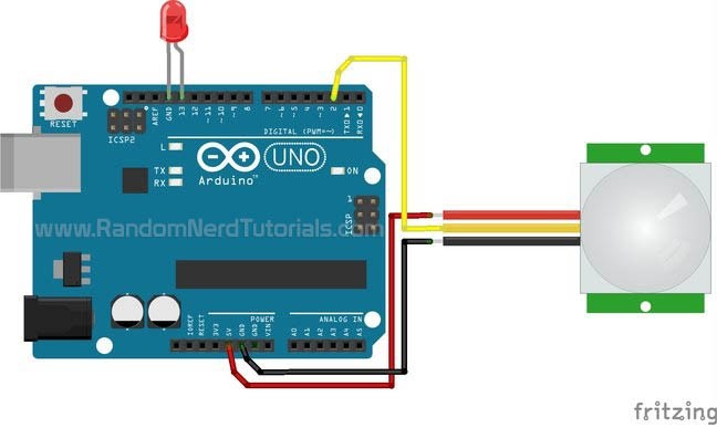
| Module pin | Arduino |
|---|---|
| VCC | 5V |
| OUT | Pin 2 |
| GND | GND |
The pin order is printed on the underside of the board, and it is not the same on every clone. Read it rather than assuming.
The two trimmers, and the jumper
Nearly every problem with this sensor is one of these three set wrongly. They are not documented on the module and most tutorials ignore them.
- 1
Sensitivity — usually the trimmer nearer the edge
Sets the range, from about 3 m to about 7 m. Turn it fully anticlockwise while you are testing on a bench, or the sensor will see you across the room and appear to trigger for no reason.
- 2
Time delay — the other trimmer
How long OUT stays high after a detection, from about 3 seconds to about 5 minutes. Fully anticlockwise is the shortest. Leave it there while testing, or you will wait minutes between triggers and conclude the sensor is broken.
- 3
The jumper — H or L
H (repeatable) re-triggers on new movement, so continued motion holds the output high. L (single) ignores movement until the delay expires. Use H for almost everything: L makes a light switch off while somebody is still in the room.
The sketch
const int sensorPin = 2;
const int ledPin    = 13;

int lastState = LOW;

void setup() {
  pinMode(sensorPin, INPUT);
  pinMode(ledPin, OUTPUT);
  Serial.begin(9600);

  // A PIR has to see a still room for up to a minute before it settles.
  // Readings before that are meaningless, and skipping this wait is why
  // people think their sensor triggers at random.
  Serial.println("Warming up - keep still for 60 seconds");
  delay(60000);
  Serial.println("Ready");
}

void loop() {
  int state = digitalRead(sensorPin);

  // Act on the CHANGE, not on the level. Printing while the pin is simply
  // high floods the serial monitor and tells you nothing new.
  if (state == HIGH && lastState == LOW) {
    digitalWrite(ledPin, HIGH);
    Serial.println("Motion");
  }
  if (state == LOW && lastState == HIGH) {
    digitalWrite(ledPin, LOW);
    Serial.println("Clear");
  }

  lastState = state;
}The one idea worth taking from this sketch is edge detection. digitalRead tells you the pin is high; comparing it with lastState tells you it has just *become* high. Acting on the change rather than the level is the difference between one clean Motion line and a thousand of them a second, and it is the same pattern you will use for every button, switch and sensor you ever read.
When it does not work
| What you see | Cause | Fix |
|---|---|---|
| Triggers constantly, nobody there | Still warming up, or sensitivity at maximum | Wait 60 s. Turn sensitivity down. Keep it away from a fan or a window. |
| Triggers once, then never again | Time delay trimmer at maximum | Turn it fully anticlockwise — it may be holding for five minutes. |
| Never triggers | Jumper wrong, or OUT on the wrong pin | Try the other jumper position. Check sensorPin. |
| Misses somebody walking straight at it | Working as designed | Mount it so people cross the view rather than approach along it. |
| Random triggers near a window | Sunlight, or a warm draught | PIR sees heat moving. Air from an AC or a heater counts. |
Where to take it
- Drive a relay instead of the LED and it is an automatic room light. Use a relay module and keep mains wiring away from the breadboard — see the warning below.
- Add a buzzer and an SD card and it is an intruder logger with a timestamp, which gives a report real results to show.
- Add an ESP32 and it sends a WhatsApp or Telegram alert, which demonstrates well and costs nothing to run.
- Pair it with an ultrasonic sensor: PIR to notice somebody is there, ultrasonic to measure how close. The PIR uses almost no power, so it can wake the rest.